90 deg Gearbox
The AW-95 helicopter plans from Vortech do not include a 90-degree gearbox. These plans are actually an evolution of the original Adams-Wilson Hobbycopter, which did feature such a gearbox. The reason for this difference is straightforward: the AW-95 was designed around the Rotax 503 engine, which is mounted vertically, eliminating the need for a right-angle gearbox. The original design, on the other hand, used a Triumph motorcycle engine with a horizontal output shaft, making a 90-degree gearbox essential.
Choosing an Engine
When I started building my AW-95, I was still a student, and budget constraints played a significant role in my decisions. Instead of using the recommended Rotax 503, I opted for a motorcycle engine as well—just like the original design. However, finding a Triumph engine proved difficult, so I went with a Yamaha XJ600 engine instead. This choice, however, meant that I had to design and build a 90-degree gearbox myself to accommodate the engine’s horizontal output shaft.
Off-the-Shelf
Initially, I explored the possibility of sourcing a ready-made gearbox. Unfortunately, all available 90-degree gearboxes I could find were heavy industrial units, completely unsuitable for an aircraft application. On top of that, they were prohibitively expensive. Given these limitations, I had little choice but to build the gearbox from scratch.
Manufacturing My Own Bevel Gears
A major challenge was sourcing the right bevel gears. Affordable, lightweight, and appropriately sized bevel gears were hard to come by, and after an extensive search, I concluded that I had to manufacture them myself. This added another layer of complexity to the project, requiring precision machining and careful design considerations to ensure efficiency and durability.
This gearbox became one of the most intricate and rewarding parts of my AW-95 build. Stay tuned as I dive deeper into the design, machining, and assembly process!
I never made gears before, and starting with bevel gears was definitely not the easiest choice—but it was the challenge I had to take on. I found a great book, "Gears and Gear Cutting," which teaches how to machine gears on manual equipment like my lathe and milling machine. The book also covers how to make the cutter itself, but that was a step too far for me—I decided to buy the cutter instead.
The first thing to consider when making gears is their dimensions, which are closely tied to the material quality. I researched several steel types suitable for gears while also making sure I could actually source them. After some iteration, I settled on two pieces of 42CrMo4 steel and started machining the gear blanks. This was done on my lathe, and I quickly realized that this steel was far tougher than anything my underpowered lathe had handled before. Each pass removed less than 0.5mm of material—not because I wanted to go slow, but because my lathe simply couldn't handle more. I broke many cutters in the process, which was financially painful to watch. In fact, I ended up machining half the blank using partly broken inserts that somehow still removed material. Only for the final passes did I use a brand-new insert to ensure the correct dimensions and surface quality.
Once the blanks were machined to spec, I spot-welded them (yes, not ideal for the material) onto another steel piece so I could clamp them properly on my indexing table. Setting everything up took a lot of time, and since I didn’t have an indexing plate, I used an Excel sheet to calculate and increment the blank’s position manually for each cut. I won’t go into the details of cutting bevel gears here—if you're interested, I highly recommend checking out the book!


Cutting the blank
I’ve never been a fan of parting off on my lathe—it’s always a bit messy, and my lathe often stalls due to lack of power (or maybe lack of skill). Still, I naively decided to give it a try. But with this steel and this size, my high-speed steel parting tool dulled before the blank had even made a full turn. Realizing this wasn’t going to work, I used a harder insert to scratch a guiding line and then cut the blank using my angle grinder—luckily, I have a big one! It made quite a mess and took some time, but in the end, I managed to cut the blank in half. After that, I machined the back side flush, and with that, the gear was mostly finished.
Final steps
Unfortunately, I didn’t take enough pictures of all the steps, but after cutting the bevel gear, I machined the top and added a keyway. Cutting the keyway with my available tooling was a challenge, and I’m not particularly proud of how it turned out. In the end, I had to resort to filing it to the final dimensions—not the most precise approach, but it worked.
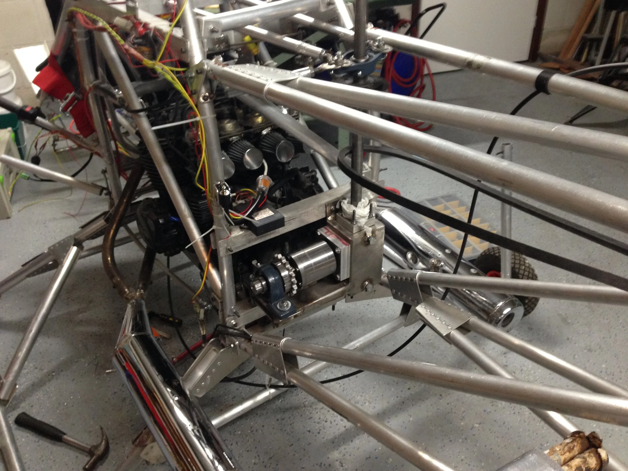
The Gearbox
The gearbox housing was built from stainless steel square tubing. It was roughly 100mm x 100mm with a thickness of 3-4mm. Most of the work involved cutting out the necessary openings and welding everything together. Unfortunately, I don’t have much documentation of this process either.
The bearing holders were straightforward aluminum blocks, machined to press-fit the bearings. Each axis was supported by conical bearings to handle axial loads. The entire assembly was sealed to allow oil lubrication. To help collect metal shavings from wear, I glued magnets inside the gearbox housing—hopefully, they’ll do their job!
The gearbox works, and I’ve run quite a bit of power through it. However, before adding oil, the sound of imperfectly meshing straight bevel gears was not great—check out the video to hear for yourself. Finally, the large lump of steel attached to the gearbox is the sprag clutch—yet another project in itself!


