The old blades
Old blades? You must have been flying for quite some time then!
I wish... but the truth is, my AW95 red ceder wood core rotor blades, will never see the sky. I’ve done extensive testing with them, running into all sorts of rotor track and balance issues. Despite my efforts, I never managed to get them off the ground. No need to panic—well, maybe just a little! I suspect the blades are dynamically unstable, and if that’s the case… there’s no fixing them. Check out the video where I mounted a GoPro on my rotor hub and pushed it to the limits—running up to flutter! The flutter is. small but audible. You can appreciate it best looking at the aluminium pitch arm plate at higher RPM’s.
The construction of my new blades is already in progress! Follow my YouTube channel, where I share all the details, or visit my website for updates!
The Plans
There are no detailed plans for the rotor blades, but their length and cross-sectional shape are specified: a standard NACA0012 profile. The rotor diameter is 19’6” (about 6 meters), with a constant chord size of 7 inches (17.8 cm). The NACA0012 airfoil coordinates are well-documented, and with today's resources, a quick Google search lets you copy-paste them instead of manually typing all those numbers.
While a symmetric airfoil like the NACA0012 isn’t the most optimized choice, it has been widely used in the early days of helicopter design. If it worked back then, it should work today!
Buying rotor blades is an option—and likely the most economical one, even before factoring in the time required to build them. But for me, the challenge is in the building, so buying was never on the table. Plus, when I started this project, I was still a student, and the cost of pre-made blades was way beyond my budget.
There are various rotor blade designs out there, with many made from aluminum. One common approach uses a thick “C” section for the spar, with two aluminum sheets riveted onto it to form the airfoil shape. The trailing edges are also riveted together. This is a more modern design—earlier versions of this helicopter actually flew with wooden blades.
Wooden blades might sound like something straight out of The Flintstones, but they’ve successfully flown many helicopters. The wooden core forms the main structure, reinforced with a fiberglass skin for added strength.
I grew up sailing, and from a young age, my father taught me how to repair my boat whenever I broke something—which happened all the time (maybe I’m not the best sailor 😆). I once built my own rudder from red cedar wood with a fiberglass laminate—essentially a small rotor blade! Having already worked with epoxy on several projects, I felt most confident using this method. So, I went with a wooden core and fiberglass skin for my rotor blades.!
Construction: The Design
Luckily, in my first year of university, I had courses in statics and mechanics of materials. I knew that building a sandwich structure from wood covered with fiberglass would result in an incredibly strong design—I had already used this approach for various reinforcements on my boat (though we often used foam as the core material). I was fairly confident my rotor blades would hold together, but I thought, why not do a basic beam calculation, just like in statics class?
A statics textbook might not be the best reference for rotor blade design, but that’s where I started. In statics, we learn to compute moment diagrams for a cantilever beam under point loads or even arbitrary distributed loads. So, I wrote a small Python program to integrate these equations and generated shear and moment diagrams.
The results? Total disaster. According to my calculations, these blades would snap in half!
I experimented with input values—especially skin thickness—easilly varied by adding layers of fiber glass but even for very thick layers, the numbers weren’t adding up. I don’t remember the exact calculations, and I’m definitely not digging up my old Python 2.7 scripts to check (can I even run them anymore? Guess we’ll never know 😆). Clearly, I was missing something.
A bit more research led me to a crucial realization: rotor blades aren’t just cantilever beams resisting shear and bending moments. They are heavily loaded in tension and don’t actually rotate in a flat plane—they fly in a cone shape with blade tips pointing slightly upward. The large centrifugal forces counteract the aerodynamic lift, ensuring that bending moments in the blade remain small enough to prevent failure. I’ll explain this in more detail when I discuss my new rotor blade design.
A Simple Thought Experiment
Sometimes, an extreme case helps clarify things. Let’s follow this one:
We want the helicopter to be as light as possible.
Therefore, all parts should be as light as possible.
That includes the rotor blades.
Now, let’s go crazy. My magic engineering skills allow me to design rotor blades with zero weight! Yes, absolutely weightless, yet still reasonably strong. Would they work?
Not at all.
With no weight, there would be no centrifugal forces. That means the only forces acting on the blades would be from aerodynamics, creating large bending moments. Even if the blades were made from solid carbon fiber, the extreme bending would likely snap them.
The Role of Weight Distribution
The key takeaway? Rotor blades need a certain weight to keep aerodynamic moments in check. This raises an important question:
💡 What is the optimal weight distribution for rotor blades?
I’ll discuss this in more detail in my New Rotor Blade Design section. But for now, the short answer is: I computed a weight distribution that minimizes bending moments and determined the ideal point masses to add for my wooden blades with fiberglass skins. The optimization assumed four discrete point masses. Of course, point masses don’t exist in reality, so I molded four lead blocks per blade and glued them in place.
Later, I refined the design without assuming point masses, but for the initial optimization, this approach was much simpler. The results? Most of the mass needed to be added near the blade tips—which makes sense, since the largest aerodynamic loads also occur there.
I regret not taking better pictures of the wooden cores with the lead weights added, so unfortunately, you’ll have to make do with these terrible, vague ones. They’re the best I’ve got!

Construction: The Core
With the design finalized, it was time to start building! This became a project of its own, with many sub-projects, all leading to one goal: getting the helicopter off the ground.
I bought red cedar wooden planks, which were already constructed from multiple glued-together pieces. This method improves stability, reducing warping or twisting over time. Red cedar is a soft wood, easy to shape—perfect for this job.
To carve the blades, I reached for an old hand tool that had been sitting in my father’s garage for years: a hand planner. My father told me it originally belonged to his father—my grandfather—so it must have been a good tool if it lasted generations. But when I see that tool, I don’t feel nostalgic or sentimental. Instead, I think, why didn’t Grandpa just buy an electric one!?
I had seen hand planners in movies, effortlessly shaving wood into perfect curls, like when the Ark of Noah was being built. It looked fantastic. In reality? Total pain.
The blade would dig in too deep or get stuck.
Other times, when I wanted it to bite, it would slide over the surface like Teflon.
After weeks of struggling, I got better at it… but years later, I tried an electric planner and realized I had wasted countless weekends shaping the rough outline of my blades. What could have been done in a few hours had taken me forever!

Refining the Shape
Once the blades were close to their final form, a finer tool was needed. I switched to a belt sander to remove most of the remaining material.
To ensure accuracy, I made a small aluminum gauge shaped like a NACA0012 airfoil, allowing me to check the surface curvature. High spots were marked and carefully sanded down. Eventually, I switched to hand sanding with large sanding blocks, ensuring an even surface without deep dents.
Was it perfect? Probably not.
But I came pretty damn close.

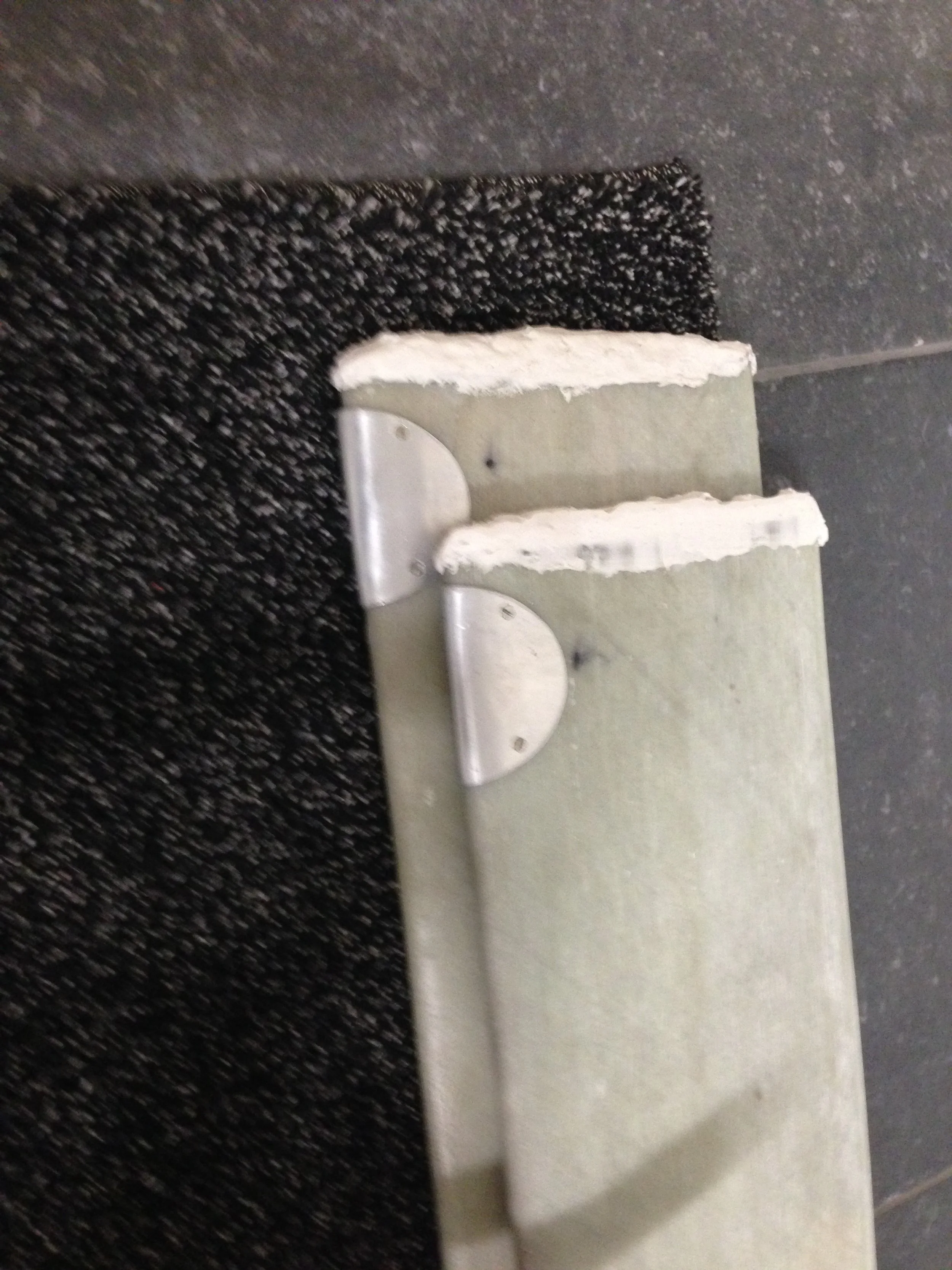
Trailing Edge
Take a look at the trailing edge in this picture! Sanding wood to a sharp edge is never really a success—it tends to splinter too easily. To improve this, I asked the wood supplier to mill a 5mm-deep slot along the center of the plank.
Before sanding anything, I filled this slot with epoxy mixed with aluminum powder as a filler. This approach allowed me to sand a sharper trailing edge. However, in hindsight, the epoxy was still not as tough as I had hoped and required careful handling. Adding some fibers to the mix would have significantly improved durability.
Later, I picked up a great trick from a highly skilled builder, who spent his career crafting top-tier racing rudders for regatta sailing teams worldwide (Jelte Kruijer: Tebsail). His method? Gluing a sail batten into the trailing edge.
Looking back, that might have been the best solution!

Construction: The Laminate
I had some experience with wet layup, but vacuum bagging was a whole different challenge! Since I needed consistent results to produce two identical blades, I had to ensure excess epoxy was properly drained while maintaining uniform layups.
I ran several experiments, but the required materials were expensive—vacuum bags, peel ply, breather material—it all added up quickly! With limited experience, I dove in. The process:
Hand-laminating the woven fabric layers using brushes and rollers on both sides of the core.
Placing a layer of peel ply, followed by breather material.
Quickly shoving everything into the bag—the epoxy was already starting to thicken!
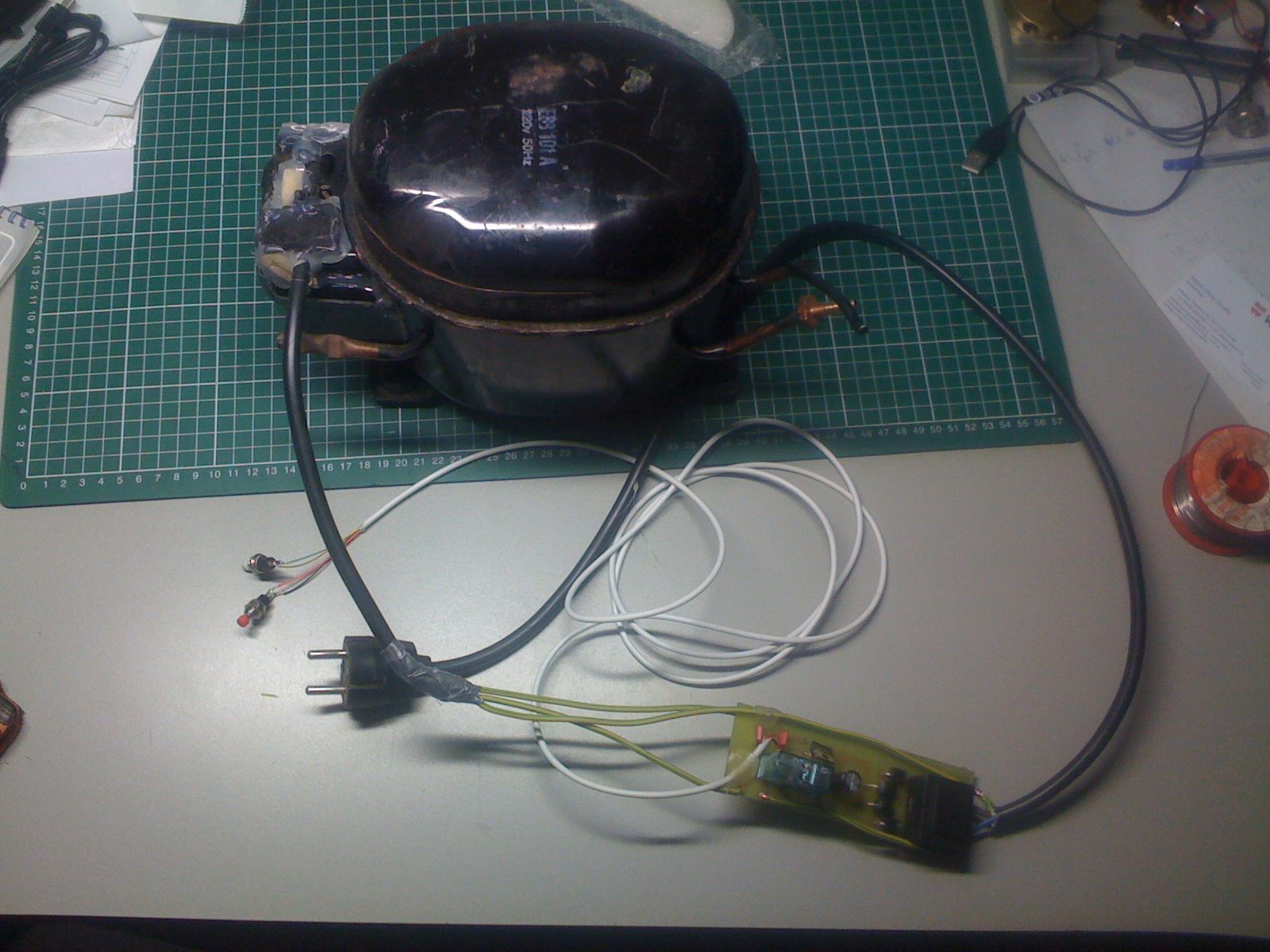
Starting the vacuum pump… and you guessed it—it didn’t start!
Absolutely fantastic. The pump worked flawlessly in all my test runs, including several unimportant test laminates. I even tested it right before mixing my insanely expensive epoxy—and then, at the worst possible moment, it failed me spectacularly!
I had built an analog Schmitt trigger circuit to control the compressor, switching it on when pressure was too high and off below a threshold. (Yes, on when pressure is high, because it's a vacuum pump… 😅). Strangely, I often see professional vacuum pumps that lack a vacuum chamber as a buffer, forcing them to run constantly—a design choice I still don’t fully understand. It only makes sense if you're aiming for absolute vacuum, in which case a bypass would be a better solution.
But back to my crisis—my pump wouldn’t start! I bypassed my Schmitt trigger circuit and connected the motor directly to the mains. Thank god, it fired up!
I dropped to my knees, looked up at the sky, and asked for one more favor: please don’t overheat tonight!
And let me tell you—these refrigerator pumps are TOUGH. It got scorching hot (I couldn’t even touch it), but it ran the entire night!


A Bit of Sanding
Rip the blade out of the bag, install it on the heli, and take off—if only it were that easy! In reality, at this point, I was probably only halfway there. I still had to:
Integrate the load introduction for the rotor head grips
Sand everything smooth
Apply a layer of lacquer
Create pockets for the balancing weights
Unfortunately, the laminate wasn’t perfect—some wrinkling had formed, especially near the leading edge, where the laminate had slightly shifted in certain spots. I had to sand these areas down and apply an extra hand-laminated glass layer over the leading edge to smooth things out.
It took hours of sanding, and by the time I was done, the entire garage was covered in dust—check the pictures! I hope my engine inlets where covered good enough! 😅


Load Introduction: Blade Grips
Computing the stresses introduced by bolts in a laminate is a complex task. I first encountered the basics of these calculations during my master's at TU Delft, the stress gradients near holes make it difficult to treat the laminate as a single material. For example the failure strength of a plate with a hole is influenced by the size of the hole, and empirical relations based on test campaigns are often the best reference.
At the time, I wasn’t fully aware of these complexities, but some failure modes are intuitive, as seen in a sketch from TU Delft. I decided to add extra laminate layers where the load would be introduced. Simple calculations with a stress concentration factor of 3 showed that I was being overly conservative, but then again, these calculations weren’t done in my prime!
I used my milling machine to align the blades and drilled holes using the grip plates as guides (see picture). After removing the plates, I drilled the holes again, this time slightly larger, to insert aluminium tubes. Once the plates and tubes were aligned, I glued the tubes into place.
To strengthen the section around the tubes, I added glass fiber bundles in two directions for both sides of the blade to account for tension and torsion. The glass fibers are great in tension, which seemed like an intuitive solution since the tubes would experience tension relative to the blade. However, computing the strength of this layup would be a real challenge, as the material properties vary across the blade, especially near the aluminium tubes. Additionally, the properties change in the Z-direction (perpendicular to the laminate), making this a complex computation task!


Final Steps
I drilled a pocket at the blade tips to allow for balancing weights. A thin aluminium plate was bent to cover the pocket, secured by four counter sunk bolts — two on top and two on the bottom of the blade. The bolts were screwed into small brass bushings, which I machined on the lathe. These bushings had a central hole that was threaded, and the outer surface was knurled to increase the surface area, after which they were glued into place. Later, I discovered that these inserts can be bought pre-made 😅, you need to know the right terminology sometimes: “Inserts”.
The pocket was sealed with a thick resin layer, which effectively concluded the structural part of the blades. For added security, I applied putty to the tips of the blades, sanding and rounding it off neatly. Given the high centrifugal forces near the blade tips, I wasn’t willing to take any chances, so I wrapped a thin layer of fiberglass fabric over the putty, securing it from top to bottom to keep it in place (no pictures available).
Finally, I applied a layer of putty over the entire blades, followed by sanding and a coat of white lacquer. This marked the completion of my first set of rotor blades!